GoldFocus - Collimation Techniques
Following is a discussion and comparison of the most commonly used collimation techniques.
GoldFocus Plus Collimation System

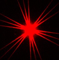
The GoldFocus Plus Collimation Mask (shown at the right) and Analysis Software are designed to measure an explicit objective quality of collimation and focus. The GoldFocus Analysis Software displays the objective measure of the image's quality of collimation and focus on the astronomer's computer screen in real-time, so that there is no guesswork regarding collimation or focus.
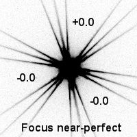
The image at the far right is a snapshot of the GoldFocus Analysis Software which shows the measured quality of collimation and focus real-time to assist in collimation and focus adjustment. In this example, the focus is near-perfect and collimation is near-perfect (near zero) in all directions.
Advantage: The quality of collimation and focus is objective, very accurate, not biased by diffraction limits nor astronomical seeing, and displayed real-time to the astronomer. The GoldFocus Plus Collimation Mask is the only collimation technique which sees and measures collimation in the exact way that your imager sees it.
Disadvantage: Requires the GoldFocus Plus Collimation Mask and Analysis Software.
"By Eye" or Star Collimation
The "By Eye" or star collimation technique here means an unassisted collimation method where the astronomer relies solely upon experience and judgment to achieve good collimation. The "By Eye" technique uses no aperture mask and the astronomer views unobstructed images of a star or stars.
The "By Eye" technique attempts to adjust collimation to make the star image(s) as small, round, and sharp as possible. The notion of a small, round star image is based upon the fact that poor collimation tends to cause coma-like aberrations in a star image which are non-round and therefore a small, round star image is associated with good collimation. When used for visual observing and not imaging, the "By Eye" technique is best used with high magnification to enhance the view of the size and shape of the star image(s). When used with a CCD imaging setup, the setup itself simultaneously determines the magnification and the critical sampling of the setup. Because good collimation must be resolved to a sub-pixel level to meet critical sampling criteria, the use of the "By Eye" technique for CCD imaging is self-limiting.
Advantage: Requires no mask or special software.
Disadvantage: Technique is subjective and accuracy is greatly diminished by the effects of diffraction limits and astronomical seeing which obscures the effects of poor collimation.
Minimum FWHM
Minimum HFD
Minimum Sigma
All three of FWHM, HFD, and Sigma are quantitative measures of the size of a star image.
The FWHM, meaning full-width at half-maximum, is the diameter of the circle around the center of the star image where the photon flux has fallen to half of the brightest intensity of the star image.
The HFD, meaning half flux diameter, is the diameter of the circle around the center of the star image which contains half of the total photon flux of the entire star image.
The Sigma (also known as star sigma or Gaussian sigma) is the standard deviation of the star image when statistically fitted to a two-dimensional Gaussian distribution.
Each of the Minimum FWHM, HFD, and Sigma techniques are similar to the "By Eye" technique in not using a mask and in trying to minimize the size of the star image. In addition, the Minimum FWHM, HFD, and Sigma techniques use a computer analysis of the star image to measure the star image size as the FWHM, HFD, and Sigma quantity, respectively. These respective star image sizes are displayed to the astronomer by computer software, usually real-time, to assist in adjusting collimation to achieve the smallest star image size.
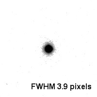
The example screen shot above-right shows how FWHM might be displayed real-time by computer software. Variations on the computer software might also analyze star images across the entire CCD image in an effort to identify the collimation center of the field of view (FOV).
Advantage: The collimation measures are quantitative and objective.
Disadvantage: The quantitative measures include the effects of diffraction limits and astronomical seeing which make these collimation measures inaccurate against the background of diffraction limits and seeing. In the case of a full image analysis, the wide flat field of focus of some superior optics further obscure the location of the collimation center of the FOV.
Defocused Star
|
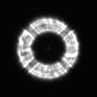
| Defocused Star: image from a Ritchey-Chrétien at extra-focus |

|
|
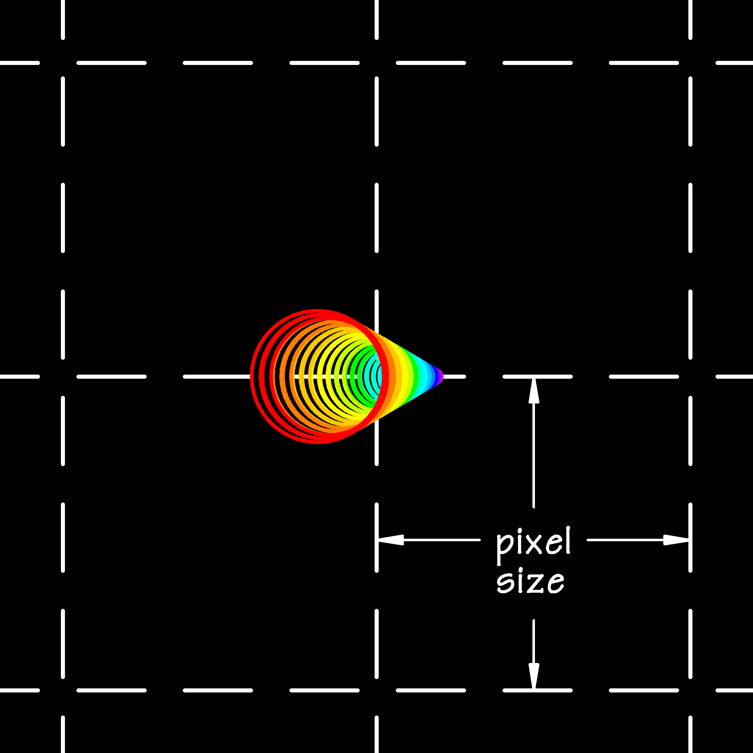
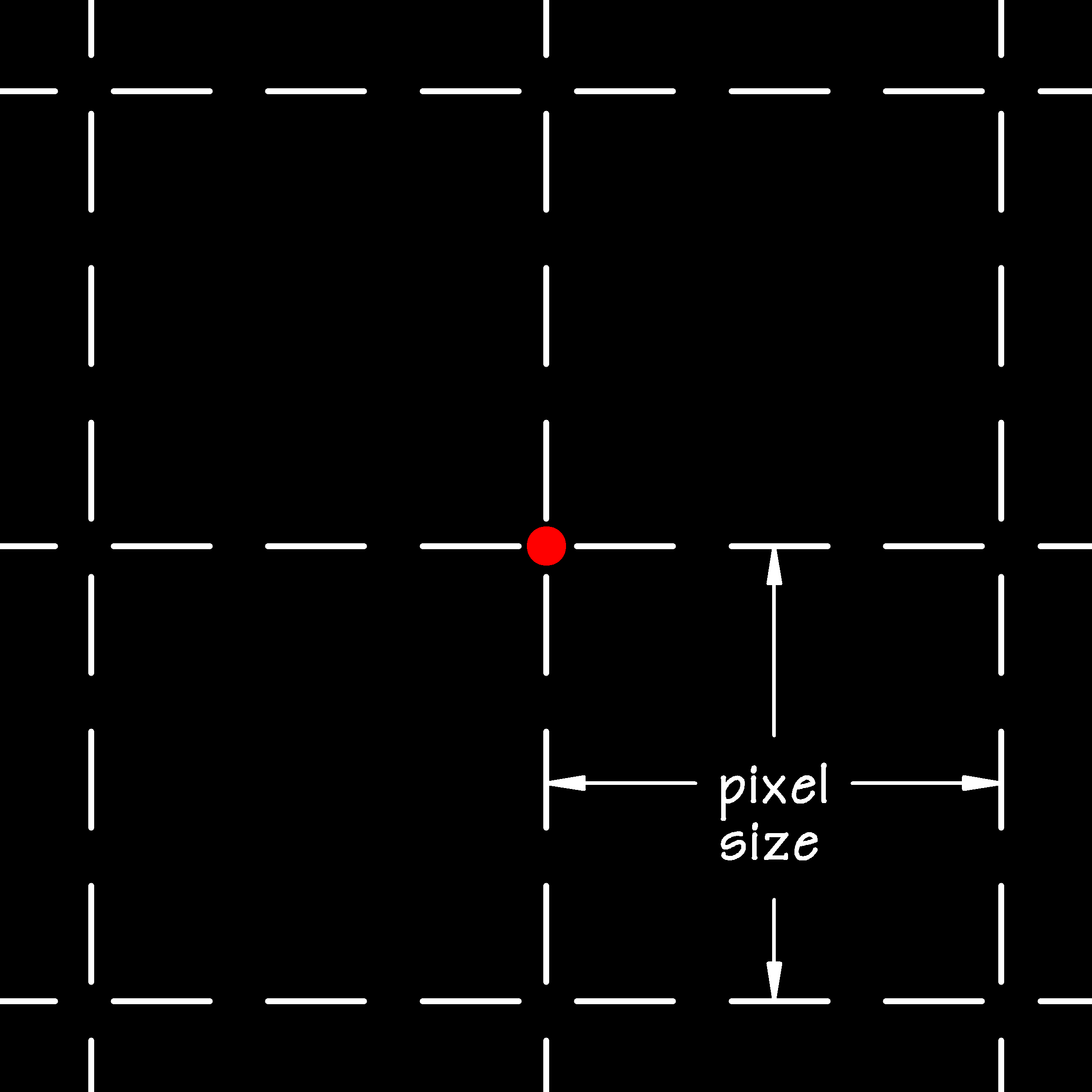
| Spot Diagram: 200 mm f/6 parabolic Newtonian, 3 mm extra-focus, primary mirror tilted by one-eighth turn of collimation screw or 88 µm, CCD pixel size 6 µm, 2.25x magnification | Spot Diagram: 200 mm f/6 parabolic Newtonian, at focus, primary mirror tilted by one-eighth turn of collimation screw or 88 µm, CCD pixel size 6 µm, 200x magnification |
|
|
| Spot Diagram: 200 mm f/6 parabolic Newtonian, 3 mm extra-focus, secondary mirror 1.3 mm off-center and exactly angled 45 degrees, CCD pixel size 6 µm, 2.25x magnification | Spot Diagram: 200 mm f/6 parabolic Newtonian, at focus, secondary mirror 1.3 mm off-center and exactly angled 45 degrees, CCD pixel size 6 µm, 200x magnification. Defocused Star is a false-negative. |
|
|
| Spot Diagram: 200 mm f/6 parabolic Newtonian, 3 mm extra-focus, secondary mirror -1.3 mm off-center (i.e., opposite of above) and exactly angled 45 degrees AND primary mirror tilted by one-eighth turn of collimation screw or 88 µm, CCD pixel size 6 µm, 2.25x magnification | Spot Diagram: 200 mm f/6 parabolic Newtonian, at focus, secondary mirror -1.3 mm off-center (i.e., opposite of above) and exactly angled 45 degrees AND primary mirror tilted by one-eighth turn of collimation screw or 88 µm, CCD pixel size 6 µm, 200x magnification. Defocused Star is a false-positive. |
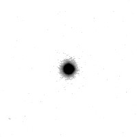
The Defocused Star technique (also called the Concentric Ring technique) uses a severely defocused star image. The technique is usually used with any system with a secondary mirror obstruction (reflectors or catadioptrics), such as in the image to the right. In principle, a severely defocused star image will show an elongation or off-center distortion when in the presence of poor collimation.
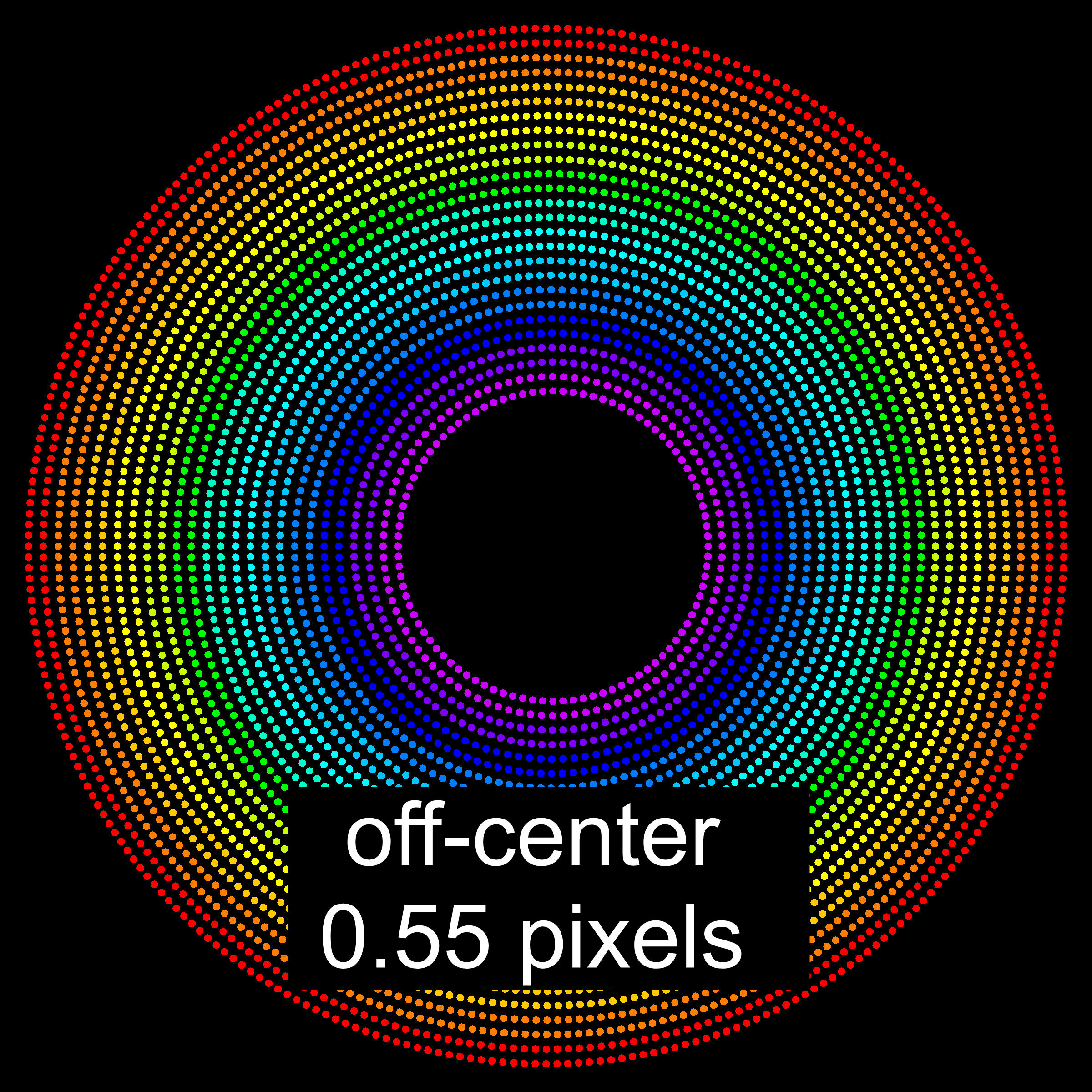
The Defocused Star technique attempts to adjust collimation to make the defocused star image as round and symmetric as possible. A major shortcoming of the Defocused Star technique is that it is very difficult to visually assess when the defocused star image is round and symmetric. In the image to the right, the dark center (the shadow of the secondary mirror) is about 1 pixel off-center from the surrounding bright ring when defocused to about 100 pixels wide. This one percent relative error is exceedingly difficult to visually identify, yet will have a significant negative effect on the image at focus.
A much more significant shortcoming is that there are circumstances where the Defocused Star technique will give false results. The Defocused Star technique can either identify a setup as being in collimation when it is not or conversely can identify a setup as being out of collimation when it is well-collimated.
Consider the three sets of spot diagrams to the right. The first set shows a Newtonian being out of collimation by the primary mirror being tilted. The out of focus spot diagram correctly identifies the poor collimation with the shadow of the secondary mirror being off-center and the at focus spot diagram showing aberrations. In this first example the Defocused Star technique has worked as intended.
The second set shows a Newtonian with the secondary mirror positioned on the spider about 1.3 mm off-center but otherwise being exactly angled at 45 degrees. Because the secondary mirror is flat, it produces absolutely no aberration from being off-center. At worst, it might produce some very minor and completely negligible vignetting. The out of focus spot diagram is virtually identical to the previous example with an actual collimation error. Thus, the Defocused Star technique incorrectly identifies the setup as having poor collimation with the shadow of the secondary mirror being off-center, yet at focus there are no aberrations whatsoever. The Defocused Star technique has given a false-negative.
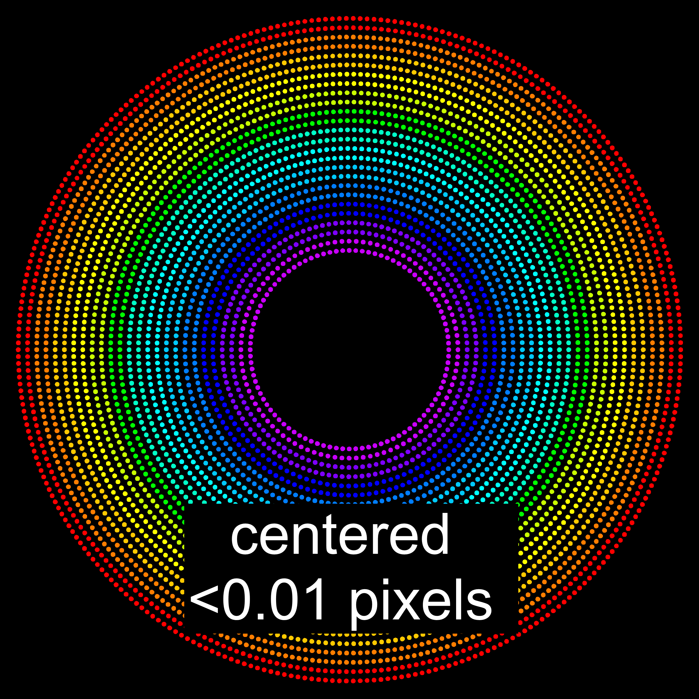
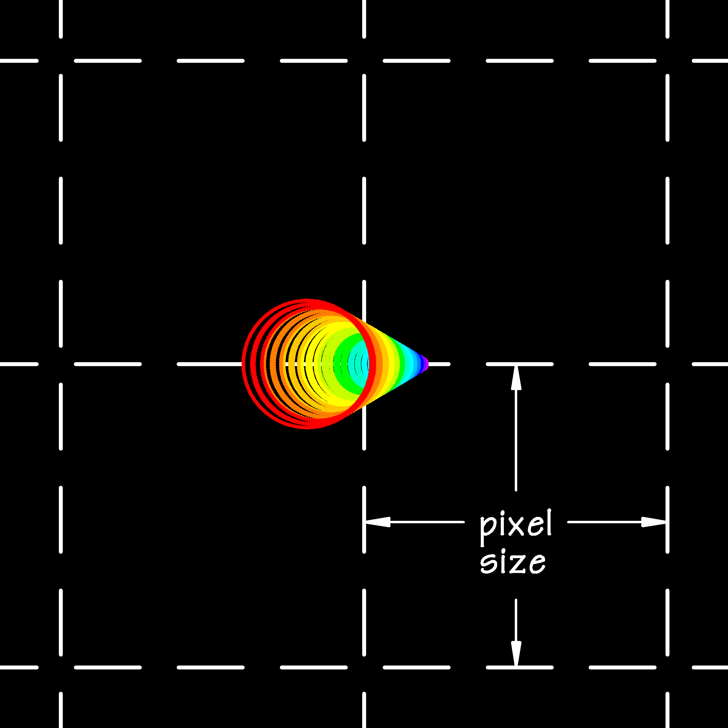
The third set shows a Newtonian with the secondary mirror being positioned on the spider about 1.3 mm off-center in a direction opposite of the second example but otherwise being exactly angled at 45 degrees and also with a primary mirror tilted as in the first example. The out of focus spot diagram shows a nearly perfectly round and concentric image, accurate to less than 0.07 microns, seemingly indicating near-perfect collimation. Yet, the spot diagram at focus shows significant aberrations. The Defocused Star technique has given a false-positive.
Advantage: Requires no mask or special software.
Disadvantage: Technique is subjective and accuracy is greatly diminished by the limitations of the human eye to detect small relative differences. Technique can produce erroneous results, either false-positives or false-negatives.
Cheshire Eyepiece and Sight Tube
Cheshire Eyepieces and Sight Tubes are tools which can be inserted into an eyepiece holder to be used for visually sighting the alignment of various optical components. Being inserted into the eyepiece holder precludes simultaneously using a Cheshire Eyepiece or Sight Tube with a CCD imager.
Due to their limited direct use with CCD imaging and the availability of on-line resources for how to use a Cheshire Eyepiece or Sight Tube, the description presented here will be very brief. In short, lensless peep-holes, cross-hairs, and outside light sources allow the user to look through and at alignments of various optical components or their reflections, such as center markers on primary mirrors, reflections from lenses, and secondary mirror's centering within OTAs.
Advantage: Inexpensive Cheshire Eyepieces or Sight Tubes ship with many amateur telescopes making them readily available. Higher quality Cheshire Eyepieces are available from several vendors at reasonable prices.
Disadvantage: Technique is subjective and visual accuracy is limited to a millimeter or two which is very unlikely to be adequate to meet CCD imaging tolerances. See the following description of the Laser Collimator for an example of the effect of this amount of inaccuracy on CCD imaging quality.
Laser Collimator
A standard Laser Collimator has much in common with a Cheshire Eyepiece except the Laser Collimator has a built-in laser pointer compared to the external light source of a Cheshire Eyepiece. The Laser Collimator also has a surface, usually marked with graduations, which is illuminated by the reflection of the laser pointer instead of aligning images or spots in the Cheshire Eyepiece. In both the Laser Collimator and the Cheshire Eyepiece the alignment is visual. Use of the Laser Collimator and Cheshire Eyepiece are similar but not identical. The reader should refer to other on-line resources for details about the use of a Laser Collimator.
|
|
| Spot Diagram: 200 mm f/6 parabolic Newtonian, at focus, collimated by Laser Collimator or Cheshire Eyepiece to accuracy of 1.4 mm off-center, CCD pixel size 6 µm, 200x magnification |
Visual accuracy of the Laser Collimator is limited to a millimeter or two. Consider a 200 mm f/6 parabolic Newtonian which is mis-collimated to be 1.4 millimeters off-center using either a Cheshire Eyepiece or a Laser Collimator, which is about the expected error of these techniques. Because the angle between an incident light ray and its reflection is twice the incident angle (see laws of reflection ), it is simple to work backwards to determine the primary mirror mis-alignment, which for this example is almost identical to the first example given above for the Defocused Star technique. The spot diagram at the right shows the aberrations caused by this collimation error. This amount of aberration is not up to the standards required by high-quality CCD imaging.
A significant caveat to the use of a Laser Collimator is that the user must be aware that the accuracy of the resulting collimation is limited by the accuracy of the alignment of the laser pointer in the manufacture of the Laser Collimator. As mentioned above the angle between an incident light ray and its reflection is twice the incident angle (see laws of reflection). Thus the laser pointer misalignment might be doubled or worse in the final collimation alignment. The user is cautioned to not read too much into the implied precision of the term 'laser' which is only as good as manufacturing tolerances.
Similar to the Cheshire Eyepiece, the Laser Collimator cannot be used with a CCD camera in-place.
Advantage: Self-contained laser light simplifies use.
Disadvantage: Technique is subjective and visual accuracy is limited to a millimeter or two which is very unlikely to be adequate to meet CCD imaging tolerances. Accuracy may be further compromised by inaccuracy in the laser pointer alignment.
Summary
Any visual collimation technique is unlikely to achieve collimation up to standards required by digital imaging. Only the GoldFocus Plus Collimation Mask and Analysis Software measures the collimation in the same way the CCD camera forms its image and has the accuracy required for high quality digital imaging.
