Refractor Collimation
This example of refractor collimation uses a 100 mm triplet apochromatic refractor telescope.
Spot Diagram
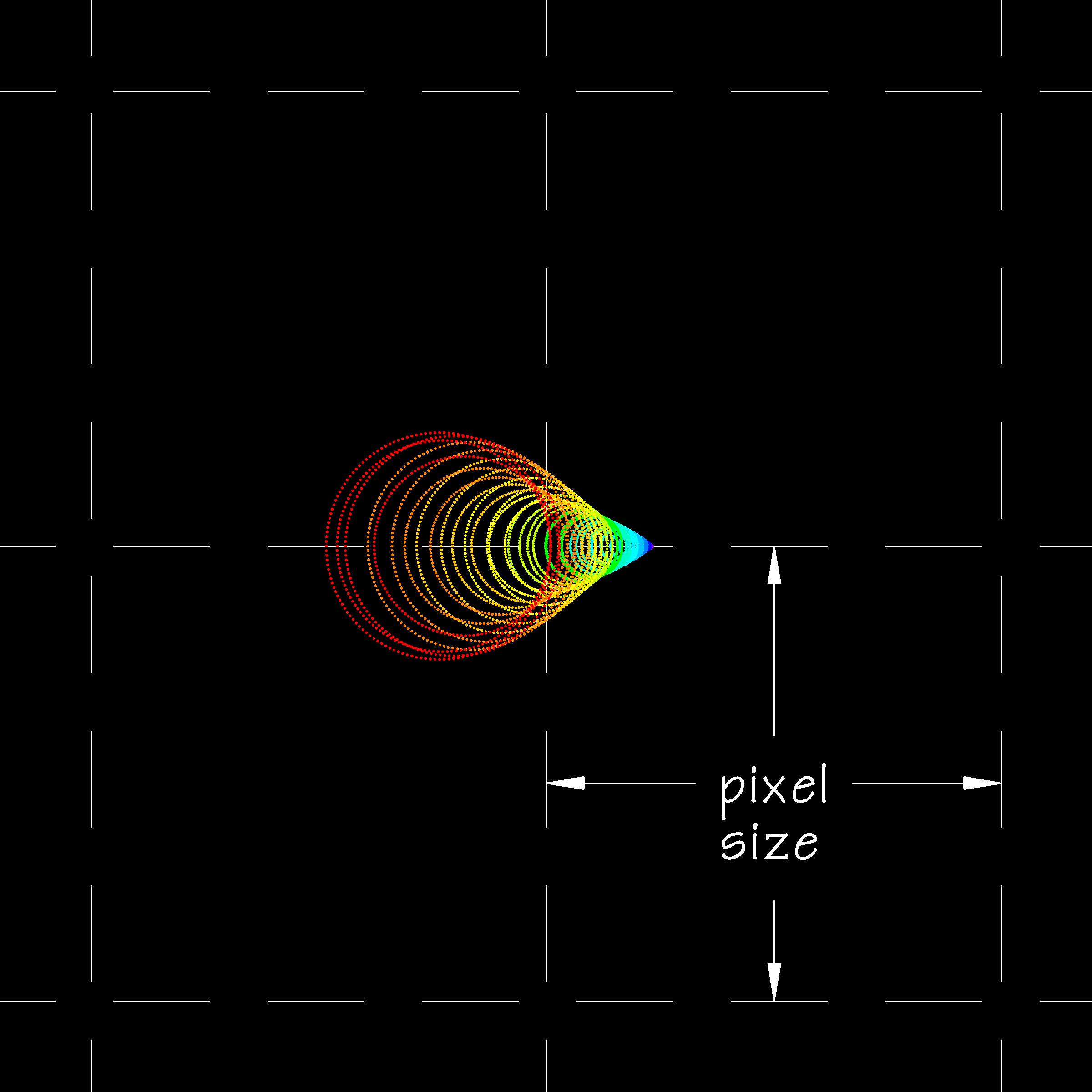
In this example the first element of the triplet is not exactly spaced but is tilted by 4 micrometers (microns) at one edge, say the lens spacer was assembled with a grain of dust under one edge. This error amounts to a very small 0.004 percent relative to the diameter of the lens. Below is the on-axis spot diagram on a CCD with 6 micrometers (microns) pixels.
|
| Spot Diagram: 100 mm triplet apochromatic refractor, first element tilted by 4 µm, CCD pixel size 6 µm |
The above image shows what should have been a pin-point sharp spot diagram spot has expanded to neaqrly a full pixel across due to a 4 micrometer (micron) misalignment of one lens of the triplet. Given that the FWHM of the Airy disk of this imaging setup is about 1.0 pixels, the aberration introduced by the misalignment is almost certainly noticeable in the final image even after astronomical seeing blurs the spot.
GoldFocus Plus Collimation Measurement
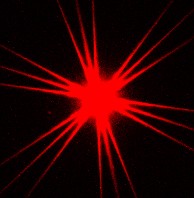
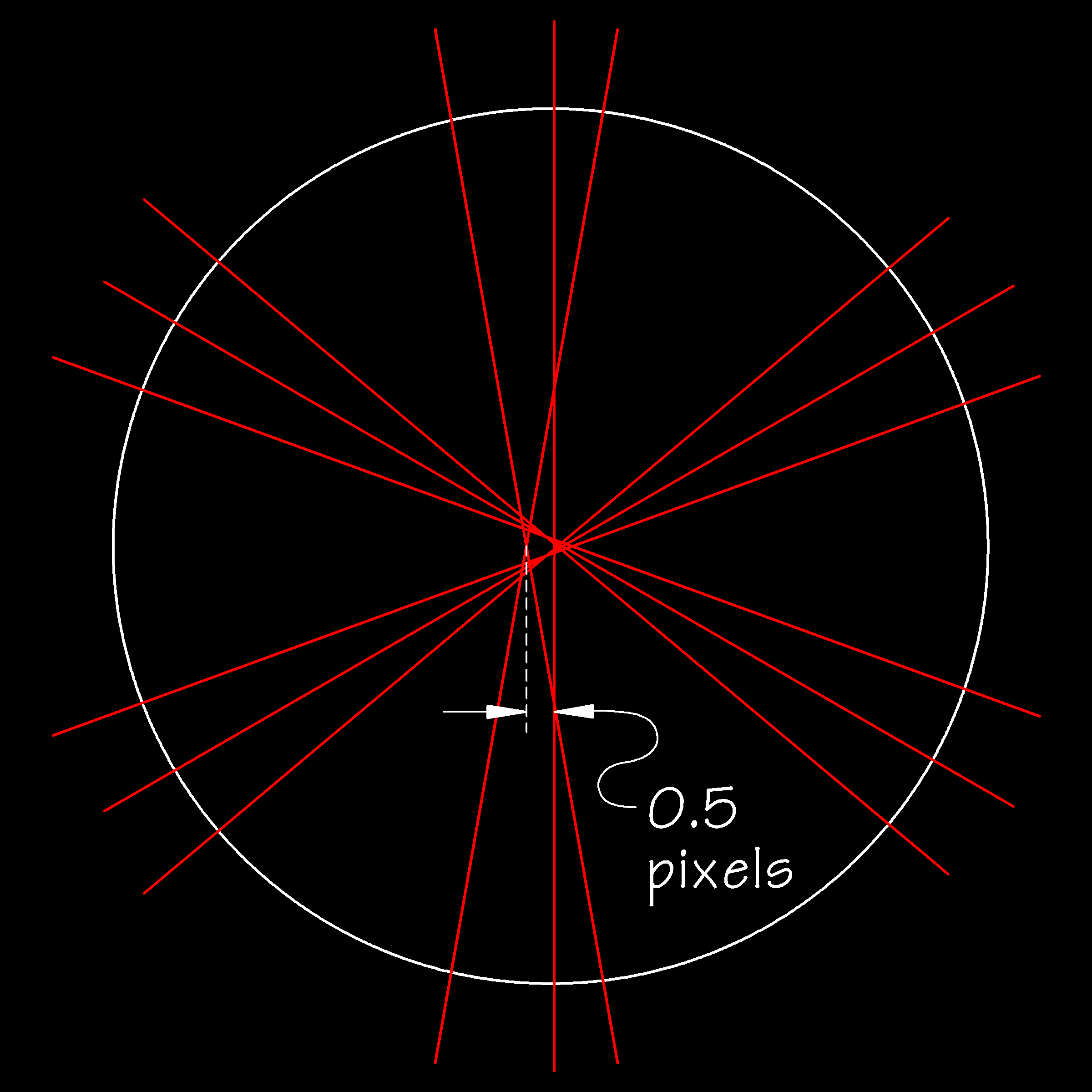
GoldFocus Plus uses a diffraction mask and analysis software to measure very specific locations in a star's diffracted spot diagram. Below is the idealized diffraction pattern of the above spot diagram for the 100 mm triplet apochromatic refractor misaligned by 4 micrometers (microns). GoldFocus Plus measures the 100 mm triplet apochromatic refractor collimation as being out by 0.5 pixels.
|
| GoldFocus Plus Collimation Measurement: 100 mm triplet apochromatic refractor, first element tilted by 4 µm, CCD pixel size 6 µm |
